Lesson 8: Let’s Learn Welding – Drawing Edition
2025/07/14
Last time, Kyappa-kun learned about the types of welding. This time, let’s dive into the basics of technical drawings!
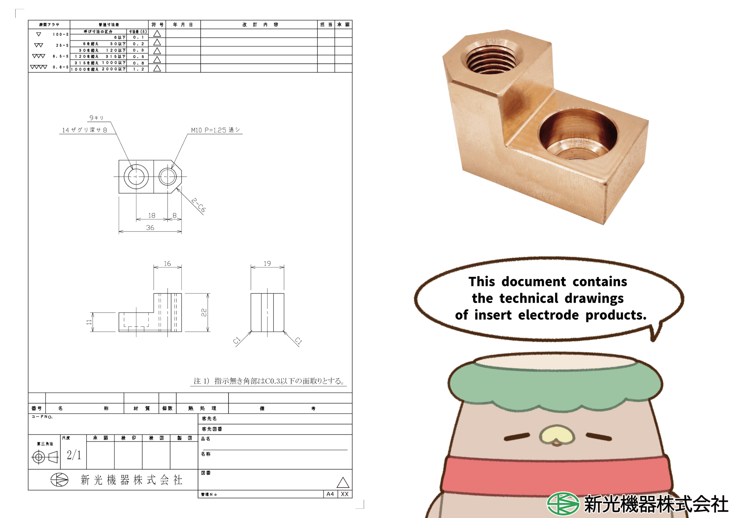
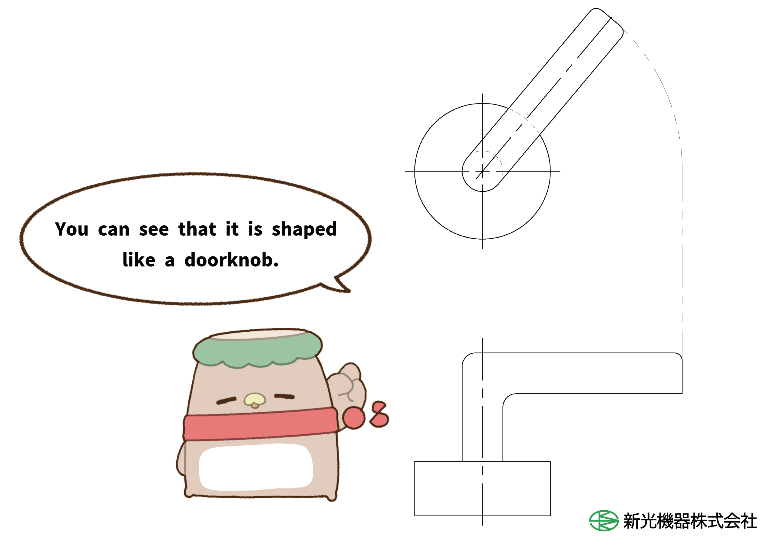
[Information Contained in Drawings]
In addition to shape, drawings include various details about the product, such as dimensions, material, and surface conditions. The method of projection (representing three-dimensional objects on a two-dimensional plane) used is the Third Angle Projection. In this method, based on the front view, the top view is placed above, and the right view is placed to the right. Let’s look at an actual drawing.
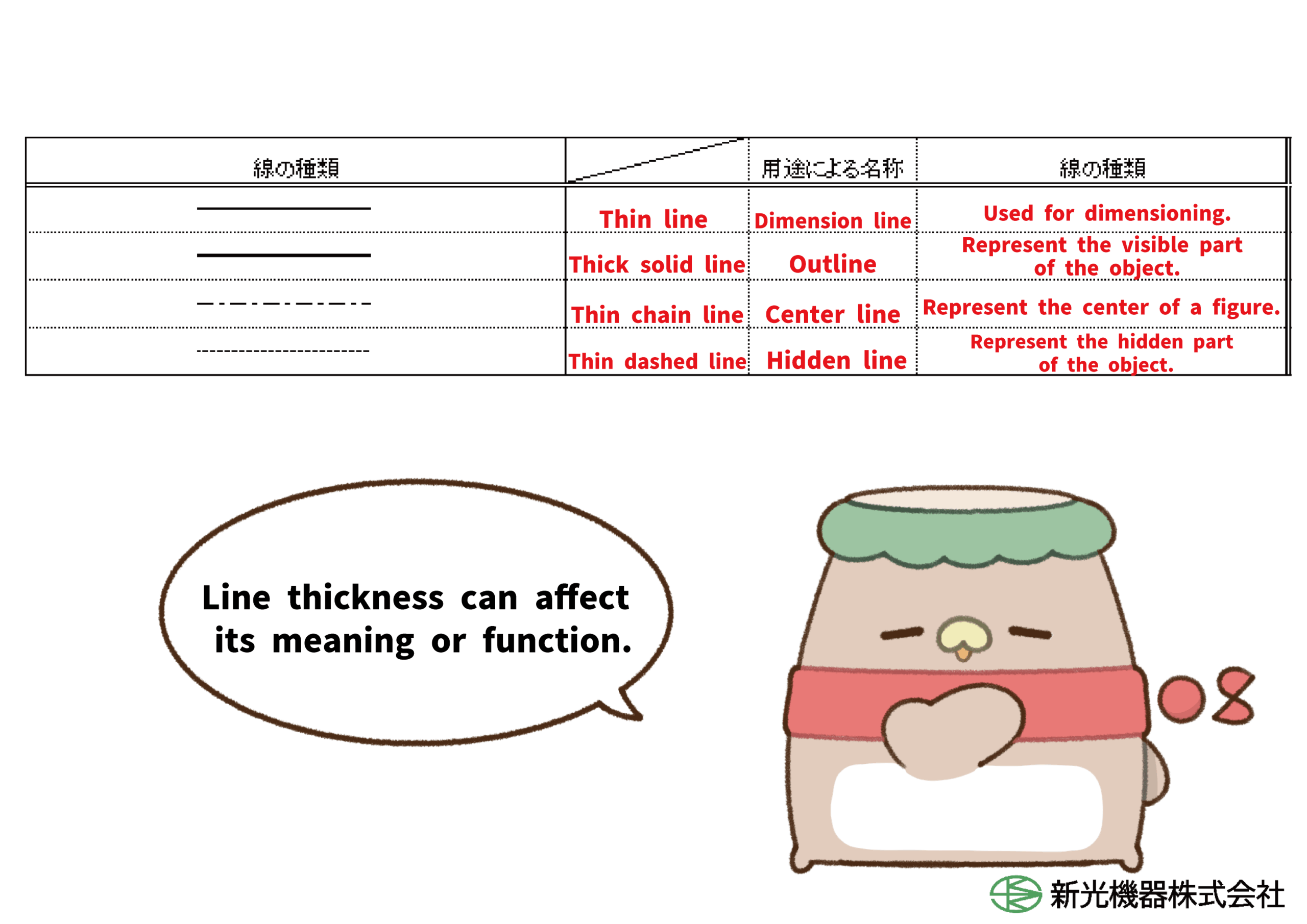
[Types of Lines and Their Meanings]
Many different types of lines are drawn, but what are their names and meanings?
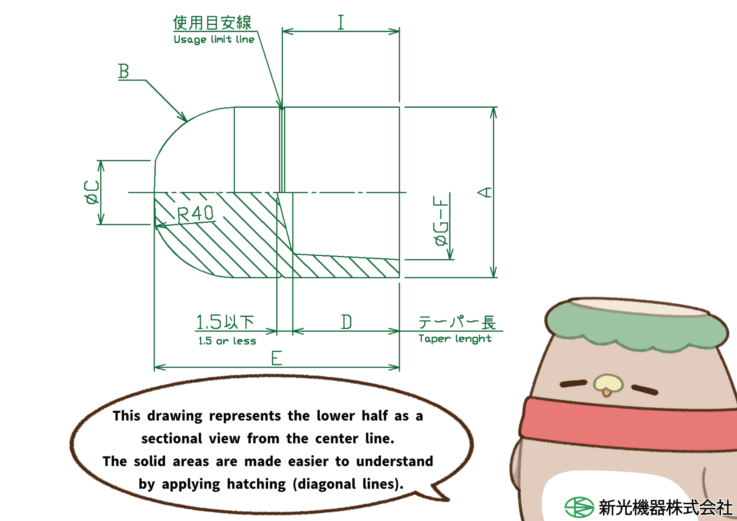
[Indicating Taper]
On technical drawings, the representation of taper is essential. A taper refers to the degree of divergence between two straight lines based on the centerline. It is indicated near the tapered area using reference lines.

“Taper 1/10” means that for every 10 mm of length in the axial direction, the diameter changes by 1 mm.
[Various Types of Drawing Representations]
Technical drawings use different types of views depending on the need.
● Main Projection View (Front View) The surface that best represents the shape and features of the object is designated as the main projection view. Based on this, additional views such as side views or top views are added as necessary.
● Section View When the internal structure or shape of an object is complex, a section view is used to illustrate it. This helps simplify the drawing by reducing unnecessary lines and making the structure easier to understand. Sometimes, cuts are made along axes that do not coincide with the centerline.
● Revolved View
For angled or slanted objects, their shapes may be difficult to interpret when drawn using standard side or top views. To improve clarity, an additional view can be created by rotating the angled portion onto a horizontal or vertical centerline, making its shape easier to understand.
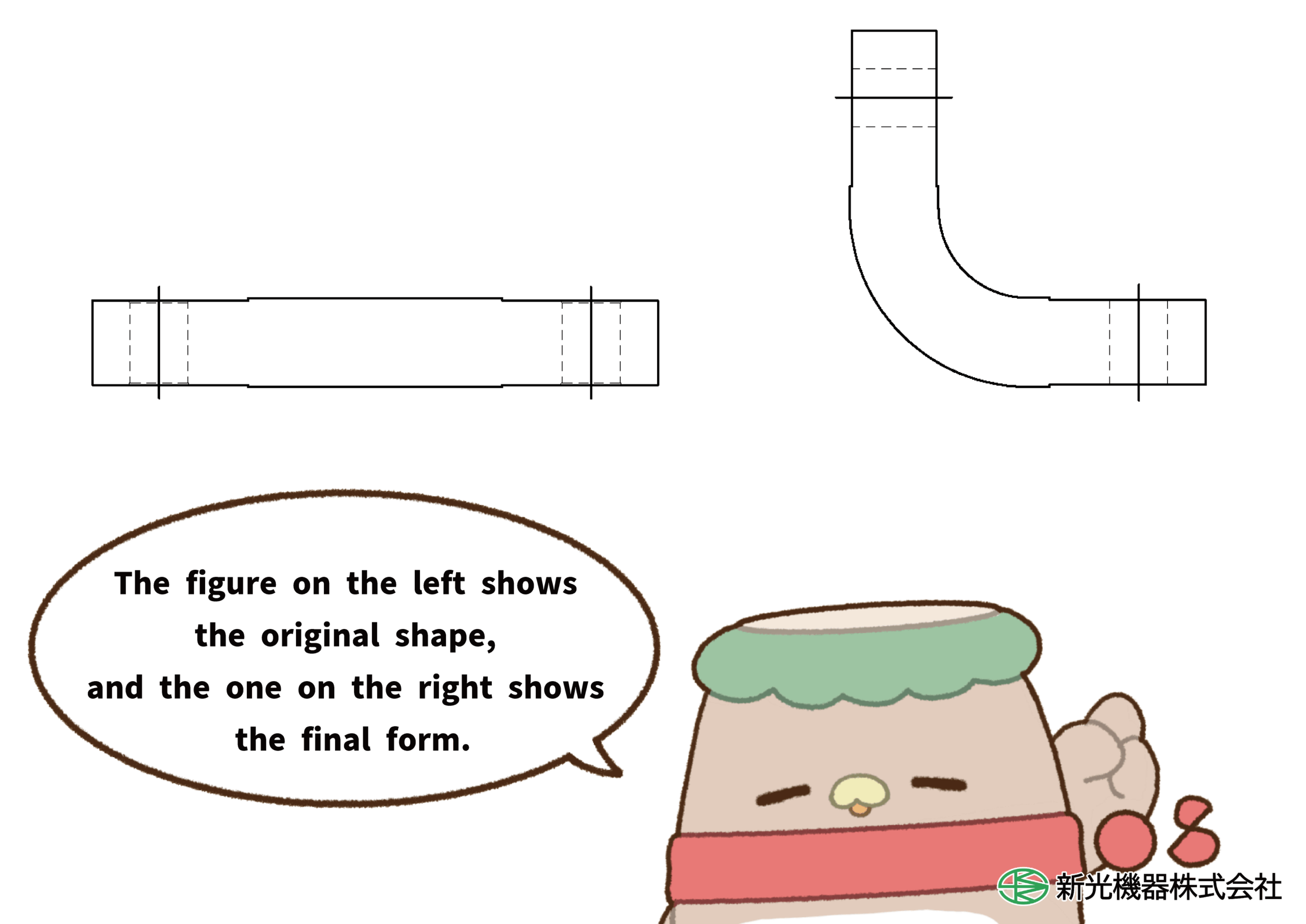
● Development View (Flat Pattern View)
In some cases, objects are manufactured by bending parts of them. To improve clarity, a development view can be added that shows the object’s shape before it is bent. When including a development view, it must be labeled as “Development View” near the drawing to clearly indicate its purpose.