Lesson 9: Let’s Learn Welding – Drawing Edition Part 2
2025/12/16
Last time, Kyappa-kun learned the basics of drawings. This time, let’s go deeper into the study of technical drawings.
Dimensioning Method
When creating a drawing, dimensions such as size, position, and angle should be clearly indicated, taking into account the movement and assembly of the object. Dimensions are expressed using dimension lines, extension lines, auxiliary symbols, and numerical values.
Dimension Line: Drawn parallel to the direction in which length or angle is measured, with terminators (arrowheads or ticks) at both ends. As a rule, different types of terminators should not be mixed.
Extension Line: Dimensions are usually indicated by placing dimension lines connected to extension lines, with the numerical value shown above the line. However, if the use of extension lines makes the drawing difficult to read, they may be omitted.
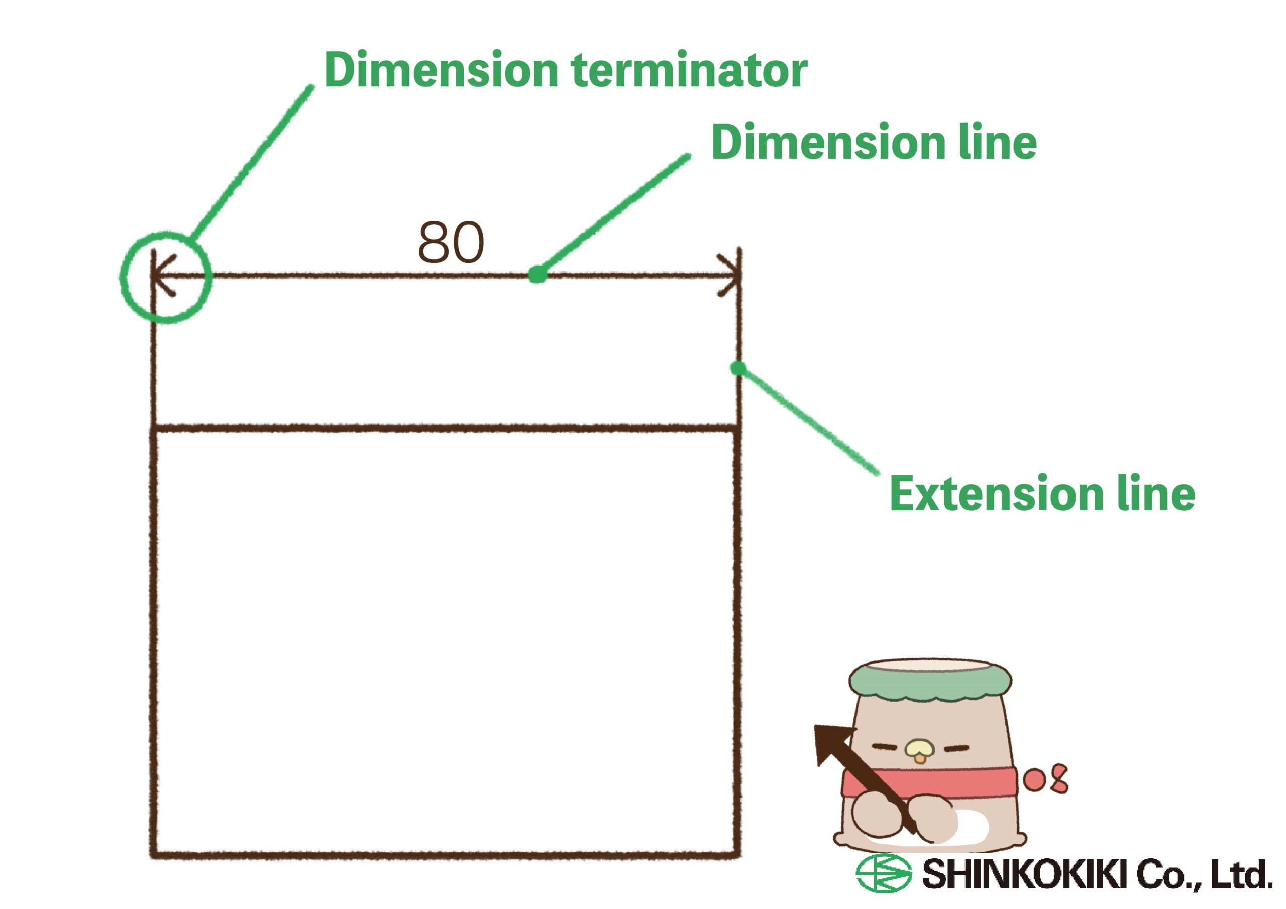
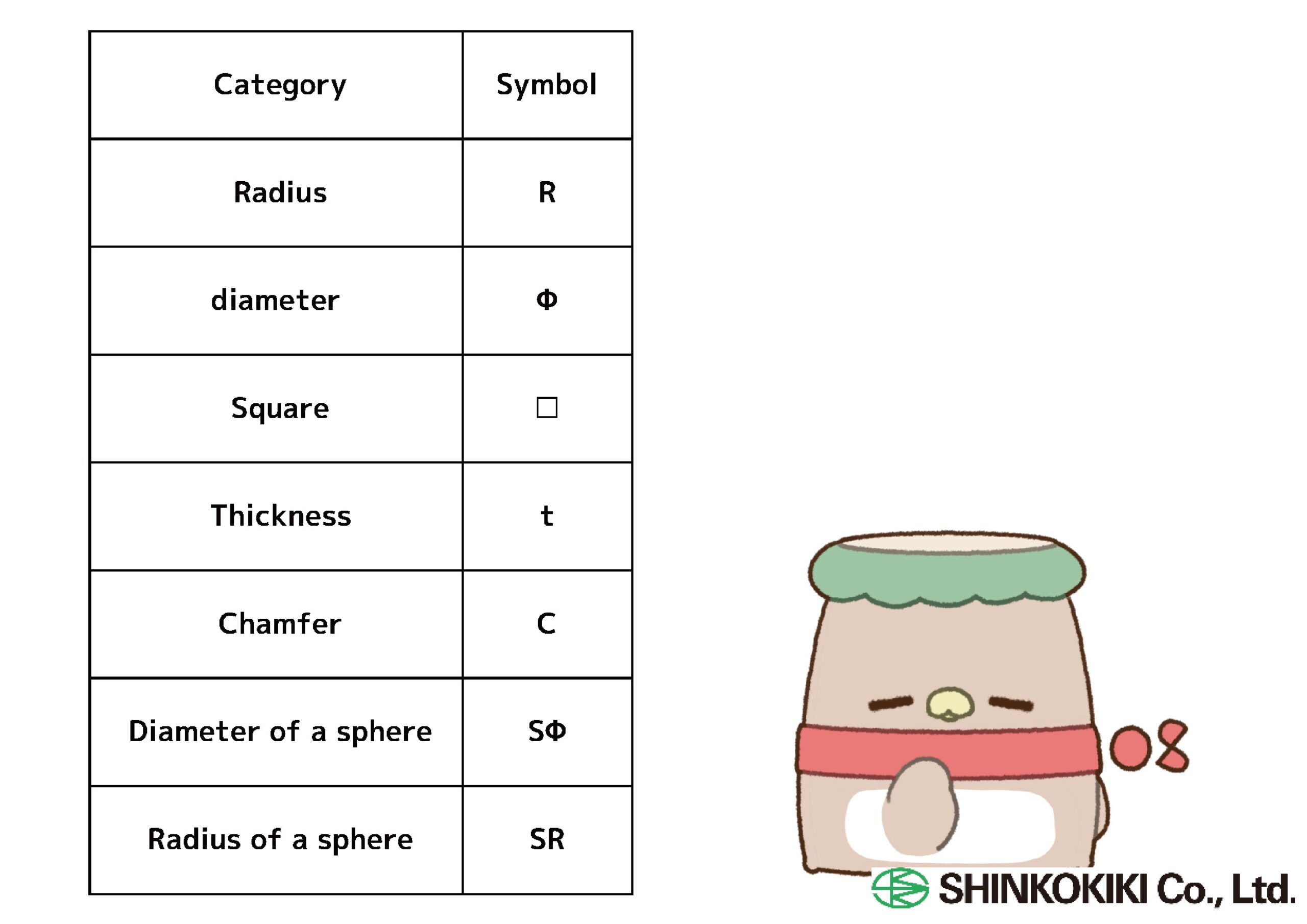
Auxiliary Dimension Symbol: A symbol used to represent a specific dimension.
Dimension Values: Length dimensions are written in millimeters, without unit symbols. Angular dimensions are written in degrees.
Dimensions should preferably be indicated on the principal projection view, and generally represent the finished dimensions of the object. They should be divided according to each process, and related dimensions should be grouped together as much as possible. The same dimension should not be repeated; however, if repetition makes the drawing easier to understand, duplicate dimensions may be included, provided they are clearly marked as such.
Tolerance
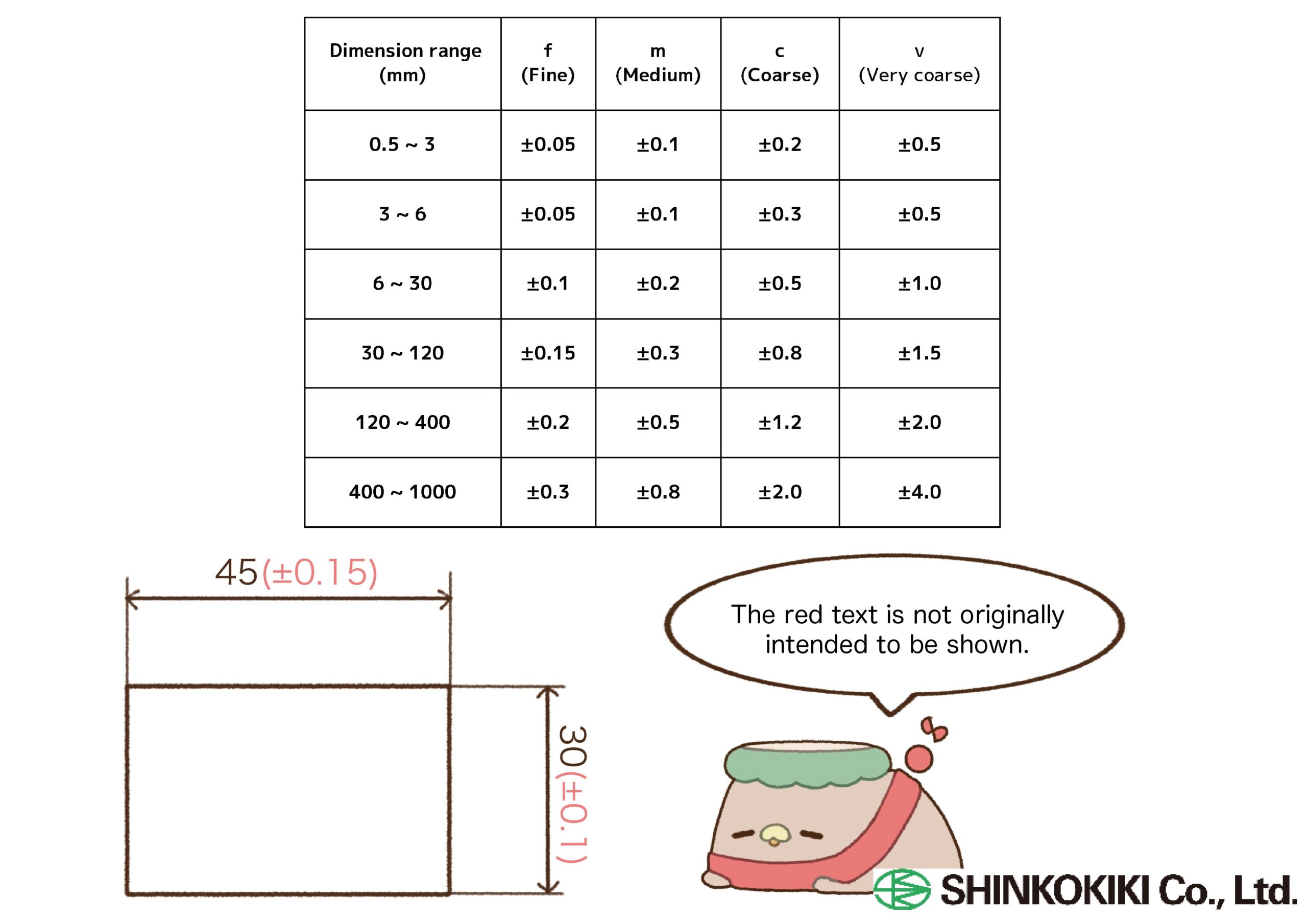
Tolerance refers to the permissible range of error allowed when cutting or processing a part. It applies not only to dimensions but also to angles and shapes, and can be classified into four types.
General Tolerance: Even in areas where no specific tolerance is indicated, permissible deviations are defined, and this is referred to as general tolerance. These tolerances are not explicitly written on the drawing.
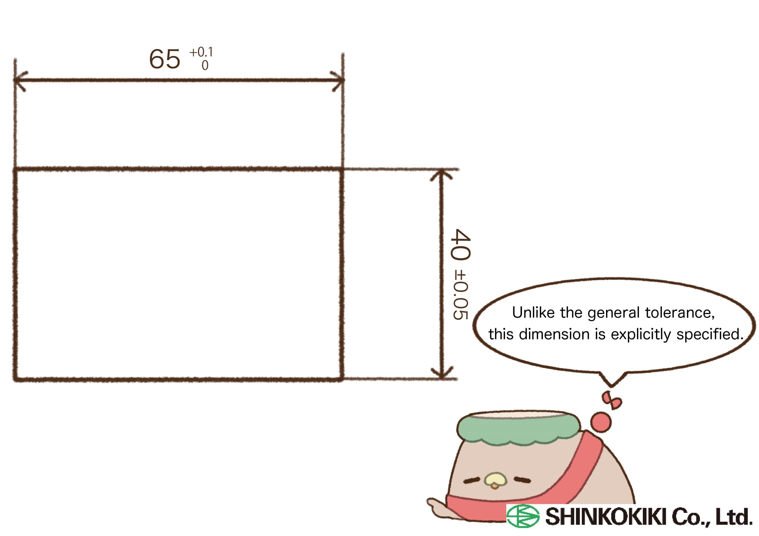
Dimensional Tolerance: Refers to the tolerance specified by the designer of the part.
Geometric Tolerance: Refers to the tolerance of an object’s angle, orientation, position, and run-out.
Fit Tolerance: Refers to the tolerance of the fit between a hole and a shaft.