Basis and Point of Resistance Welding (1)
1.History and Subject of development of Resistance Welding
About 10 years after the butt welding invented in 1885, the spot welding method, which is the Lap welding method that a lapped soft steels are put together directly between copper alloy electrode and created the welding portion of point condition ( nugget ) are formed by concentration to the small one point with large amperes of electricity was invented. The spot welding has very fast welding speed and simple action. As the automatic operation is very easy and brief moment, the major welding method for a thin plate welding are widely developed.
Specially, in the production of automotive body required absolute necessity of low cost ad mass production. Although the press accuracy is not so severe and a little bit of plate space is occurred. By the press is provided by clamping two or more overlapping sheets between two electrodes widely recognized and applies as a most suitable welding method for the high productivity and mass production basis. Following to the spot welding, the projection welding or seam welding were invented and conquered the lap welding resistance welding in the fields of the thin plate welding. The projection welding is multiple points simultaneously welding method by the butt in the steel plate side, due to a narrow parts, plural gun positions are difficult. The seam welding is forming continuous airtight welding rotating disc type electrodes.
In the world of the spot welding, the era as a subject for bare soft steel was continued during long time, there was no fata problem so far. The spot welding theory established at the era of bare soft steel plates are to be said that the delay of the spot welding technology thereafter, due to potential latent of the problems by the steel special quality of most suitable for the spot welding.
For the protection of the rust, the galvanized steel which is now widely used was low nugget forming capability or as a purpose of light weight or to provide high safety against collision, the high tensile steel plate ( HITEN ) was introduced in the market. It is difficult to say that it is solved the problem with current spot welding technology of the high tensile steel plate ( HITEN ) of unrealistic high pressured condition etc. It might be necessary of fundamental reexamination of the welding phenomenon without stopgap measure.
Shinkokiki Co., Ltd., is always considering to be able to the help of the various customers at any rate through the enlightenment of basic technology or the consultation of the problem.
(1-1) Position of classification of the resistance welding and kinds
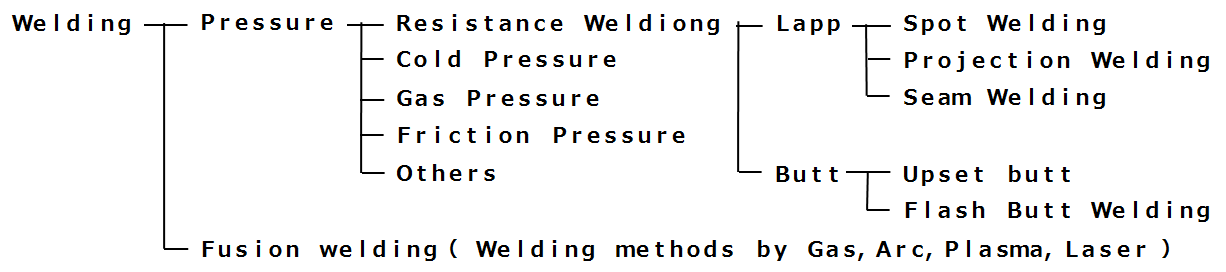
(1-2) Kinds of the stack resistance welding and component, welding principle , features
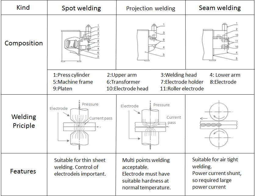
(1-3) Merit and demerit of major welding method of the spot welding

![]()
2. Transition and progress of the spot welding
The initial spot welding machines were almost of all stationary spot welding machine and portable spot welding machine was transferred by a manpower. From initial period the spot welding machine was automated by the control equipment called TIMER which was the movement of pressure-electric current-open and were widely used, as the worker’s skill was not necessary.
When the mass production era of automotive production was come, the big scale multi spot welding machines were developed. This machine had the function that the many welding points could be simultaneously by many guns. The equipment renewal fee were vast and long construction period were required at every new model change. And gradually the tendency was going to be shifted to the robotic system of general-purpose spot welding machine. The initial stage of the spot welding robot was same as man power operation’s portable spot welding machine that only welding gun was transferred by the robot and the supply of electricity was made by the welding transformer hanging from the ceiling with the connection of heavy stiff cables.
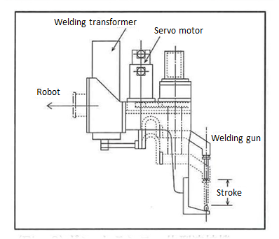
The complete change of the welding robot’s form and performance was the gun & built-in transformer type welding machine loarded the welding robot. The light weight welding transformer of long time pending matter was achieved by the inverter DC type welding machine. Using the exchange of the commercial frequency of 50 Hz or 60 Hz to high frequency of about 1000Hz by the inverter control, the magnetic path sectional area of the welding transformer was made smaller to about one of twentieth ( 1/20 ). Now, even though the simple single AC welding machine of the regular current control of welding current is common.
And now is the era of 3 time electrification control of preheat-permanent current-after heat and my computer timer of also additionally installed.is standard performance. It is the maximum subject that the improvement of the spot welding core technology precisely so as to be able to utilize the performance level up of the welding machine.
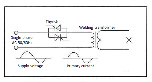
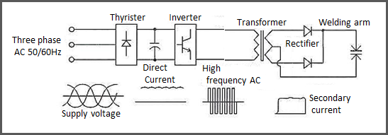
(2-1) Principal electric circuit and working sequence at the spot welding machine
|
|
■ Control of welding electric current and time, pressure Once welding condition is decided, supply of welding electric current and weld time etc will be fixed by controller so-called Welding timer. Control on electric current is popular by phase control on Thyristor. Pressure control is by air regulator in case of air pressure system. But recently welding gun by electric system using servo motor is increasing. |
|
|
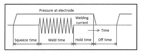
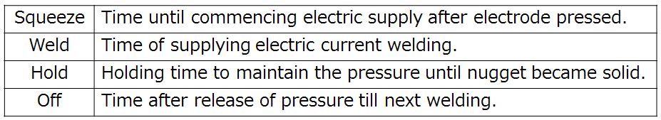
■ Definition of the word for time control
|
(2-2) Gun & Transformer integrated welding machine for loading welding robot
|
|
The system of Gun & Transformer integrated welding machine loaded on welding robot is rapidy increasing mainly at automobile manufacturing industries. Inverter DC welding machine with lightweighted transformer by application of high frequency enable to accept lower robot loading weight/capacity than before.
|
![]()
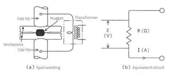
3. The principle of the spot welding and required thermal features
The principle of the spot welding is very simple. However, it is impossible to observe directly by the naked eyes the fusion zone or as the change of the temperature rise and expansion of current path are simultaneously occurred within very extreme short time. It is fugitive by the human being’s ordinary feeling and sometimes it causes the illusion.
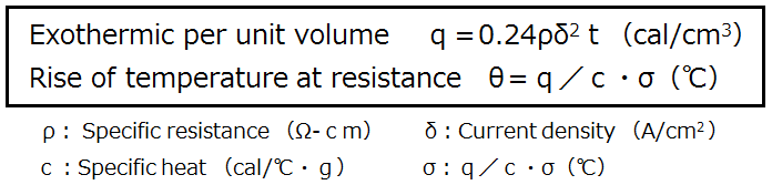
The thermal features required to the high level spot welding is selected heating and realization of steep temperature slope against to the electrode side. There is no other comparison welding method.The rise f the temperature of the fusion zone is decided by the exothermic heat per unit q=0.24ρδ2t(cal/cm3). The exothermic per unit time is the proposition of the product ρδ2 to specific resistance ρ and second power of current density δ.ρδ2(W)is called exothermic heat density and the center of the fusion zone and the electrode portion of a few 10 mm distance separated is indeed its volume of several hundred times. This difference is not by chance and it is created with the intention artificially. It is used the difference expansion element. That is to say ① As a electrode material. The selection of higher copper alloy of conductivity and thermal conductivity. ② The higher current density of the fusion zone is made by thin tip portion. ③ Due to short time electrification, the cooling effect is not reached to the fuzion zone, the rise of specific resistance ρ along to resistance temperature curve.
In the galvanized steel sheet, the extreme selected exothermic heat at the weld interface and the collapse of the heat features required in the spot welding of the steep temperature inclination to the electrode side, it is easy to happen various problems of the growth delay of the nugget, increase of welding expulsion and occurrence of sticking ( adhesion of electrode and sheet ). To solve these problems, there is no other way of realization ” to make the start-up speed earlier”,” to make the chain of effective resistance exothermic heat as much as possible so as to use the increase of specific resistance ρ along with the temperature rise of the fusion zone “. It is necessary to invention of the welding of condition and electrode shape.
When the era of the subject of the spot welding is bare soft steel sheet only, the selected exothermic of the welding interface and the steep temperature inclination against the electrode is gained naturally without any feeling about what is the heat features required the spot welding. As the bulge called the naval was shaped in the center portion of electrode tip, the higher current density was secured in the weld interface even if the expansion of the apparent tip diameter was made. Although the kinds of steel sheet was changed, the thermal property required to the spot welding was not changed. It is desired from daily work to achieve further higher quality spot welding including the reconsideration of current spot welding.
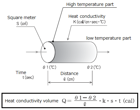
(3-1) Exothermic heat density around spot welding position based on formula on resistance exothermic heat
|
|
■ Exothermal heat density is high at the gap of the work periodically and it willreach to melting point. |

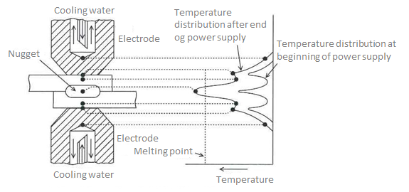
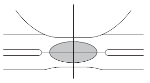
(3-2) Temperature distribution at spot weldingposition caused by heat incination
|
(Fig・7) Heat density of spot welding position The electrode having big thermalcapacity and high heat conductivity will work as strong cooing device and temperatu distribution wil be shownithe left figure. In case of Zinc plating sheet, heat inclination is low. The temperature between wokpiece and electrode also becoe high and they will be desposited. |
|
|
|